- 您现在的位置:买卖IC网 > Sheet目录478 > MMA8451QT (Freescale Semiconductor)IC ACCELEROMETER 3AXIS 16QFN
�� �
�
�2�
�2.1�
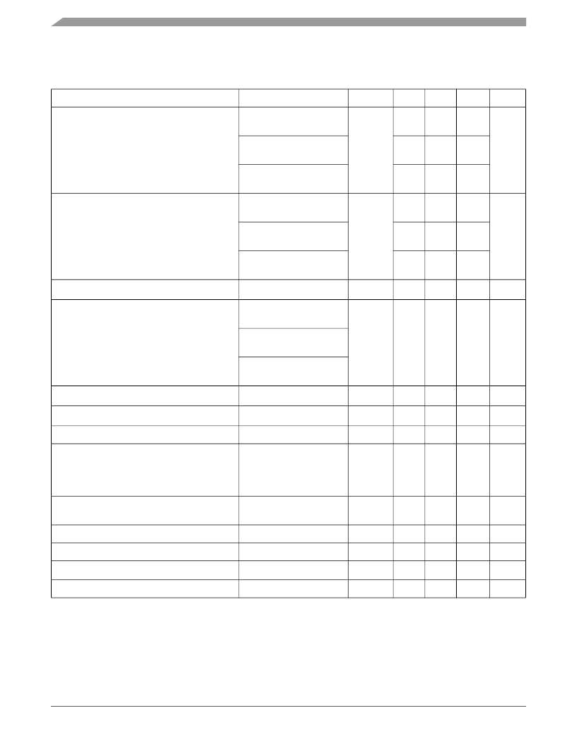
�Mechanical� and� Electrical� Specifications�
�Mechanical� Characteristics�
�Table� 2.� Mechanical� Characteristics� @� VDD� =� 2.5V,� VDDIO� =� 1.8V,� T� =� 25°C� unless� otherwise� noted� .�
�Parameter�
�Test� Conditions�
�Symbol�
�Min�
�Typ�
�Max�
�Unit�
�FS[1:0]� set� to� 00�
�2g� Mode�
�±2�
�Measurement� Range� (1)�
�FS[1:0]� set� to� 01�
�4g� Mode�
�FS�
�±4�
�g�
�FS[1:0]� set� to� 10�
�8g� Mode�
�FS[1:0]� set� to� 00�
�2g� Mode�
�±8�
�4096�
�Sensitivity�
�FS[1:0]� set� to� 01�
�4g� Mode�
�So�
�2048�
�counts/g�
�FS[1:0]� set� to� 10�
�8g� Mode�
�1024�
�Sensitivity� Accuracy� (2)�
�Soa�
�±2.64�
�%�
�FS[1:0]� set� to� 00�
�2g� Mode�
�Sensitivity� Change� vs.� Temperature�
�FS[1:0]� set� to� 01�
�4g� Mode�
�TCSo�
�±0.008�
�%/°C�
�FS[1:0]� set� to� 10�
�8g� Mode�
�Zero-g� Level� Offset� Accuracy� (3)�
�Zero-g� Level� Offset� Accuracy� Post� Board� Mount� (4)�
�Zero-g� Level� Change� vs.� Temperature�
�FS[1:0]� 2g,� 4g,� 8g�
�FS[1:0]� 2g,� 4g,� 8g�
�-40°C� to� 85°C�
�TyOff�
�TyOffPBM�
�TCOff�
�±17�
�±20�
�±0.15�
�mg�
�mg�
�mg/°C�
�Self-Test� Output� Change� (5)�
�X�
�Y�
�FS[1:0]� set� to� 0�
�4g� Mode�
�Vst�
�+181�
�+255�
�LSB�
�Z�
�+1680�
�ODR� Accuracy�
�2� MHz� Clock�
�±2�
�%�
�Output� Data� Bandwidth�
�BW�
�ODR/3�
�ODR/2�
�Hz�
�Output� Noise�
�Output� Noise� Low� Noise� Mode� (1)�
�Normal� Mode� ODR� =� 400� Hz�
�Normal� Mode� ODR� =� 400� Hz�
�Noise�
�Noise�
�126�
�99�
�μg/� √� Hz�
�μg/� √� Hz�
�Operating� Temperature� Range�
�Top�
�-40�
�+85�
�°C�
�1.� Dynamic� Range� is� limited� to� 4g� when� the� Low� Noise� bit� in� Register� 0x2A,� bit� 2� is� set.�
�2.� Sensitivity� remains� in� spec� as� stated,� but� changing� Oversampling� mode� to� Low� Power� causes� 3%� sensitivity� shift.� This� behavior� is� also� seen�
�when� changing� from� 800� Hz� to� any� other� data� rate� in� the� Normal,� Low� Noise� +� Low� Power� or� High� Resolution� mode.�
�3.� Before� board� mount.�
�4.� Post� Board� Mount� Offset� Specifications� are� based� on� an� 8� Layer� PCB,� relative� to� 25°C.�
�5.� Self-Test� is� one� direction� only.�
�MMA8451Q�
�Sensors�
�6�
�Freescale� Semiconductor,� Inc.�
�发布紧急采购,3分钟左右您将得到回复。
相关PDF资料
MMA8452QR1
IC ACCELER 2G/4G/8G 3AXIS 16QFN
MMA8453QR1
IC ACCELER 2G/4G/8G 3AXIS 16QFN
MMBF0201NLT1
MOSFET N-CH 20V 300MA SOT-23
MMBF170-7
MOSFET N-CH 60V 500MA SOT23-3
MMBF170LT1
MOSFET N-CH 60V 500MA SOT-23
MMBF170
MOSFET N-CH 60V 500MA SOT-23
MMBF2201NT1
MOSFET N-CH 20V 300MA SOT-323
MMBF2202PT1
MOSFET P-CH 20V 300MA SOT-323
相关代理商/技术参数
MMA8452Q
制造商:FREESCALE 制造商全称:Freescale Semiconductor, Inc 功能描述:3-Axis, 12-bit/8-bit Digital Accelerometer
MMA8452QR1
功能描述:加速计 - 板上安装 LOW G 3-AXIS 12BT EX VLT
RoHS:否 制造商:Murata 传感轴:Double 加速:12 g 灵敏度: 封装 / 箱体: 输出类型:Analog 数字输出 - 位数:11 bit 电源电压-最大:5.25 V 电源电压-最小:4.75 V 电源电流:4 mA 最大工作温度:+ 125 C 最小工作温度:- 40 C
MMA8452QT
功能描述:加速计 - 板上安装 LOW G 3-AXIS 12BT EX VLT
RoHS:否 制造商:Murata 传感轴:Double 加速:12 g 灵敏度: 封装 / 箱体: 输出类型:Analog 数字输出 - 位数:11 bit 电源电压-最大:5.25 V 电源电压-最小:4.75 V 电源电流:4 mA 最大工作温度:+ 125 C 最小工作温度:- 40 C
MMA8453Q
制造商:FREESCALE 制造商全称:Freescale Semiconductor, Inc 功能描述:Xtrinsic MMA8453Q 3-Axis, 10-bit/8-bit Digital Accelerometer
MMA8453QR1
功能描述:加速计 - 板上安装 LOW G 3-AXIS DGTL ACCEL
RoHS:否 制造商:Murata 传感轴:Double 加速:12 g 灵敏度: 封装 / 箱体: 输出类型:Analog 数字输出 - 位数:11 bit 电源电压-最大:5.25 V 电源电压-最小:4.75 V 电源电流:4 mA 最大工作温度:+ 125 C 最小工作温度:- 40 C
MMA8453QT
功能描述:加速计 - 板上安装 LOW G 3-AXIS DGTL ACCEL
RoHS:否 制造商:Murata 传感轴:Double 加速:12 g 灵敏度: 封装 / 箱体: 输出类型:Analog 数字输出 - 位数:11 bit 电源电压-最大:5.25 V 电源电压-最小:4.75 V 电源电流:4 mA 最大工作温度:+ 125 C 最小工作温度:- 40 C
MMA8491Q
制造商:FREESCALE 制造商全称:Freescale Semiconductor, Inc 功能描述:Xtrinsic MMA8491Q 3-Axis Multifunction Digital Accelerometer
MMA8491QR1
功能描述:加速计 - 板上安装 3-Axis Low Voltage Discrete Tilt Sensor
RoHS:否 制造商:Murata 传感轴:Double 加速:12 g 灵敏度: 封装 / 箱体: 输出类型:Analog 数字输出 - 位数:11 bit 电源电压-最大:5.25 V 电源电压-最小:4.75 V 电源电流:4 mA 最大工作温度:+ 125 C 最小工作温度:- 40 C